Wednesday, May 31, 2006

Pimp My Ride!: The Other Installs


I installed component speakers and a crossover in the front door of G8rmni. There are tons of how-to's on the net already, so I won't go into detail on the installation.

Here is a photo of the driver-side door with three layers of Fat Mat on it. I installed the Infinity crossover in the middle of the door, just above the cross beam with industrial-strength Velcro.

I should also mention that about a month after using the Pioneer AVIC-N2 headunit, the newer AVIC-N3 was released.

I decided I'd buy the newest stereo and sell the old one on E-bay. The stereo install and hideaway unit replacement took about one hour to perform since all of the wiring was already done.

Thursday, May 11, 2006

Pimp My Ride! Part VI: Bluetooth Phone & Finish


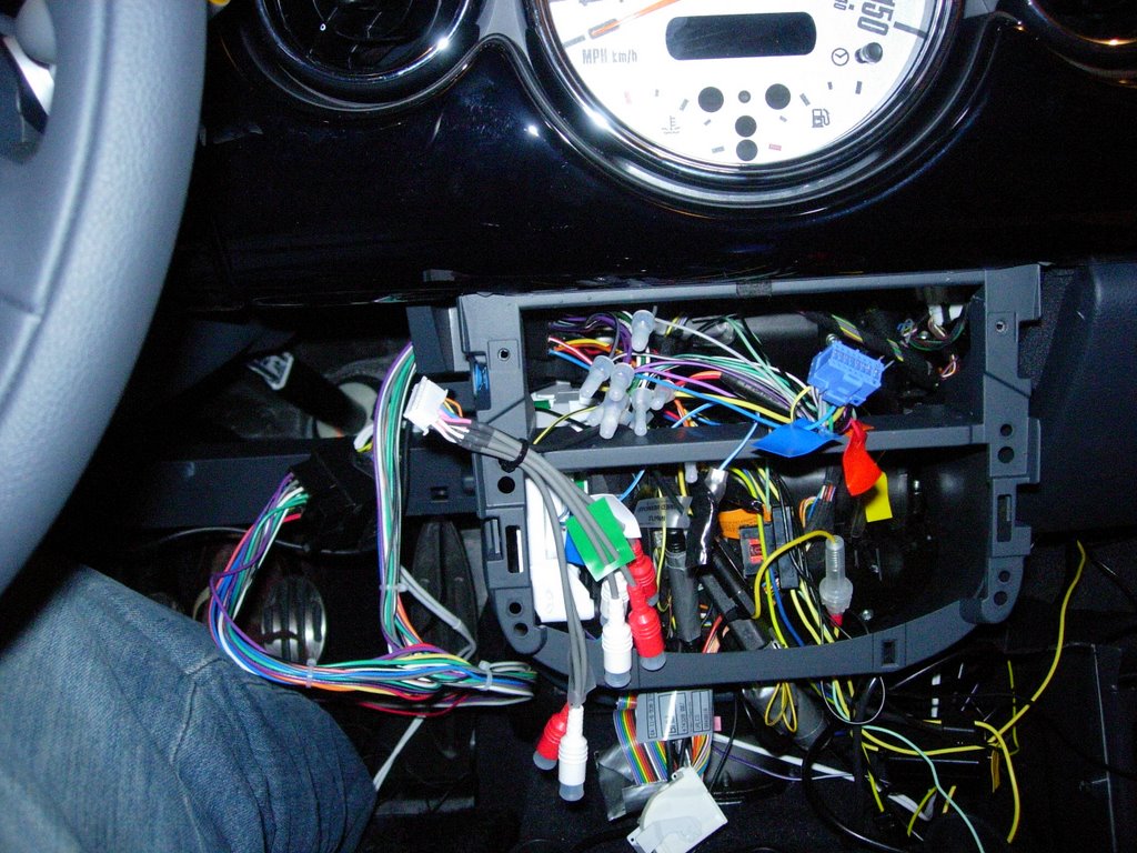
Now that you have Ian's adaptor installed you can button the center console and dash back up.

I bought a Parrot Bluetooth adaptor from Mikey the MINI so that I could use it with a Parrot Evolution 3000 hands free kit and the phone buttons on my steering wheel.

Seeing as how MINI of Sterling wanted to charge me two grand for a similar setup, I think spending $300 on parts for this little convenience is a bargain.

There is not much to the hands free kit install.

I mounted the blue Parrot "brain" unit in the side of the dash on the driver's side. There is a panel on the end of the dash that you can access when the door is open. Use a panel remover tool to pop it open.

I used some Industrial Velcro and carpet foam to make a snug, rattle-free fit for the gadget in the little space. Once you have wedged the blue box in the dash, you should only have one wire coming out of the side of the dash (the hands-free kit's mic).


I mounted my mic with the included mount and 3M tape in the driver side A-pillar, making sure to tuck the wire behind the pillar.

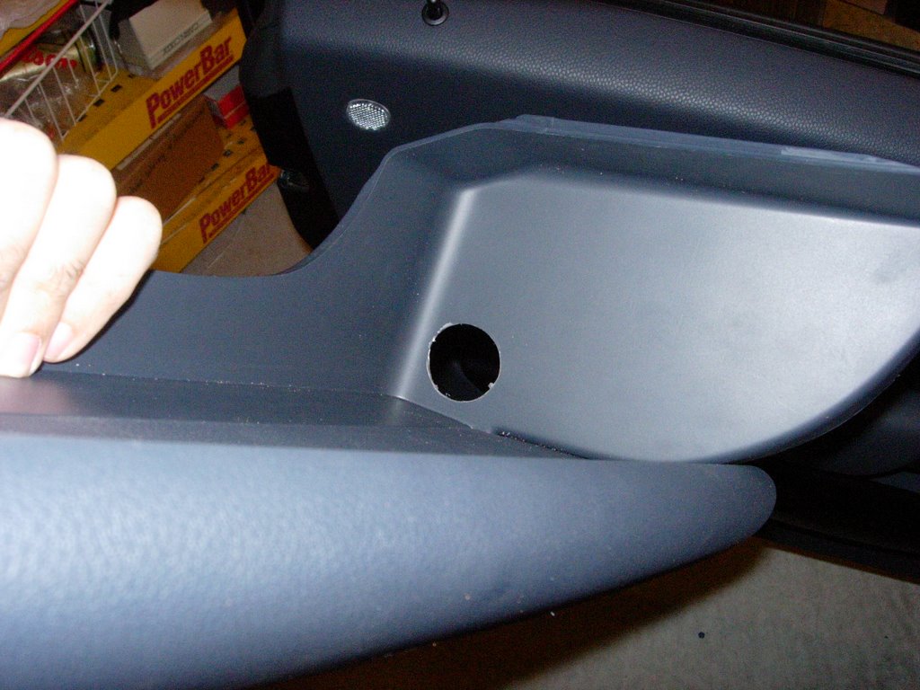
I decided to install the Euro Parcel Shelf that comes stock on European-spec MINIs in place of the lame, stock knee bolster.

The knee bolster is really easy to install. Simply line up the grooves on it's base and ram it into place. It takes about ten seconds (well, for me it took two minutes -- I drilled a hole in the side of it so my iPod adaptor wire could fit through easily).

That's it!

I learned a lot about my car and it's construction after going through this mod. I have to admit, I was nervous about tearing open my first brand new car, but my anxiety was alleviated as the project progressed.

If there is one piece of advice I can give to other first-time installers like myself, it is:

"Take your time and you will do a bang-up job."

Tuesday, May 09, 2006

Pimp My Ride! Part V: Ian Cull's Auto-Up Adaptor


Installing Ian Cull's Auto-Up Window Circuit is much easier than installing the reverse, emergecny brake and speed pulse wires. Trust me.

There are two ways to plug the adaptor into the back of the toggle switch bay: blind install (Ian explains this on his site) and not-so-blind install.

I opted for the latter.

There are to little clips that keep the A/C panel firmly in place. Use your thumb to squeeze these inwards and the A/C panel will drop out. Now you can remove the toggle panel in the same fashion.

Unplug the wire-ribbon that connects to the back of the toggle panel and plug it into the circuit board of Ian's adaptor.

Next, plug the circuit ribbon into the back of the toggle panel.

Stuff the circuit board into the dash and set the toggle panel in place. Make sure to "click" the A/C panel back in place as well.

That's it!

Monday, May 08, 2006

Pimp My Ride! Part IV: Button Up the Stereo


After you've made sure all of your wiring harnesses are spliced/plugged in, (I used a MFSW adaptor from Mikey the MINI, along with a Parrot Bluetooth MFSW adaptor from him) connect them to the AVIC-N2 headunit.

If you went the same route as me, you will have what seems like just TOO many wires. Have no fear; there is a solution for this.

You'll want to remove the knee bolster that is beneath the steering wheel in order to find a place to stick all of those wires and adaptors.

To remove the bolster, grip the panel and give a sharp tug straight down. It may require a significant amount of force, so don't worry about really laying into it.

Now that you have the bolster out of the way, reach around to the back of the stereo through the opening you created by removing the knee bolster. Pull the wires and harnesses through.

The headunit should now have enough room to slide into it's DIN chassis.

Once you have the stereo with it's adaptor plate in place, go ahead and screw it in using the same Torkx screws you removed over two hours ago :).

I used electrician's tape to secure all of the wires and adaptors beneath the steering column. you can attach them to the plastic bar that runs horizontally below the steering column. See the photo below to see what bar I am referring to.


Next up, installing Ian Cull's Auto-Up Window Adaptor ...

Pimp My Ride! Part III: Emergency Brake Wire


Installing the emergency brake wire took a little creativity on my part.

The emergency brake wire is located underneath the emergency brake boot. To remove the boot, squeeze the plastic trim inwards. After a little finagelling it should pop out, allowing you a view of a wire that connects to the E-brake.

Grab a flashlight and shine it into the rear area of the handbrake. You will notice some metal parts that appear to be copper or gold. These metal parts carry enough current to give the Pioneer's E-brake wire a signal.

I knew I needed to attach the wire to the little copper-looking parts inside the e-brake container, but my fingers are way too small to fit down there and soilder the wire...

No problem.

Hide the E-brake wire as best you can, making sure it is threaded through the bottom of the E-brake console.

Strip a foot (yes, 12") off of the end of the Pioneer E-brake wire. Twist the bare wire to give it stiffness. Next, bend the bottom third of the wire into a "J."

Dip your J-shaped wire down into the e-brake container and thread it through one of the copper-looking metal parts. Once you get the wire threaded through a piece of the E-brake metal, you should be able to tie it off on itself. Don't worry about the wire touching anything else and starting a fire. The current is too low and there is nothing else to conduct electricity within the plastic container.

Pimp My Ride! Part II: Reverse & Speed Pulse Wires

The reverse wire (image below) is located below the doorsill panel on the passenger side. You may have to lift up some of the thick carpet to access the green wire. The light green wire is the one you want, not the dark green one.


Now that you have the sill kick panel, passenger seatbelt and rubber seal door trim, walk or crawl over to the driver's side of the car and remove the same three things. You have to do this in order to access the speed pulse sensor.

The speed pulse sensor wire tells the Pioneer hideaway unit that your car is in motion. Without this wire connected, you will not be able to use all of the features on the touch screen (i.e., side acceleration, angular velocity, etc.).

The little gizmo that Pioneer included to attach the hideaway unit's speed pulse wire to the car's speed pulse wire is pretty Mickey Mouse. Instead of using the supplied clamping mechanism, I just cut and stripped the car's wire and spliced the Pioneer wire to it. A quick squeeze on a crimp cap and no one is the wiser.

Unfortunately, I do not have a photo of the speed pulse wire. All you need to know is that the MINI's speed pulse wire is a baby poo brown/orange color. There will be a weird gaggle of wires in the sill that look this color. Any one of them will do. Use my method of strip, splice and crimp to attach the wire.